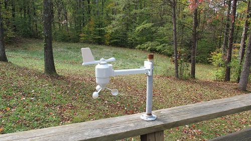
Arduino Uno, 433MhzRx и метеостанция Oregon Scientific WMR86
Этот проект позволяет обрабатывать сигналы 433 МГц от метеостанции Oregon Scientific WMR86 и декодировать их в простые десятичные значения с помощью Arduino Uno. Значения для направления ветра, скорости ветра, температуры, влажности, ультрафиолетового света и осадков затем отправляются через USB / последовательный порт Arduino на хост-компьютер.
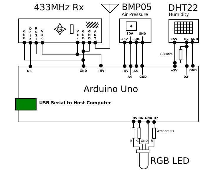
 Arduino непрерывно прослушивает трансляции трех датчиков WMR86 (датчик ультрафиолетового света необходимо приобретать отдельно) и объединяет их каждую минуту для вывода строки CSV. В пакете WMR86 имеется три передатчика: Направление ветра + Скорость ветра (среднее значение и порывы ветра), Температура + Влажность и Количество осадков (совокупный итог и скорость). Каждый из них имеет разные периоды между передачами, например, Ветер каждые 14 секунд, Температура / Гул и Дождь в более длительные периоды. Это приводит к перекрытию сенсорных передач и неизбежному повреждению некоторых пакетов, однако протокол имеет простую арифметическую контрольную сумму, основанную на nybbles, которая помогает устранить большинство неверных данных. По общему признанию, вероятность ошибок замещения, приводящих к тому, что неверные данные остаются необнаруженными, намного выше, чем если бы использовался более высокий бит CRC, основанный на полиномиальном процессе
 Продление проекта
Несколько функций стали желательными после того, как оригинальная система работала в течение нескольких лет. Основной проблемой было отсутствие индикаторов уровня заряда батареи, а также отсутствие прямой обратной связи от модуля Arduino о принимаемых сигналах. Решение было решено двумя способами, но с участием аналогичных частей программы.
Уровень заряда батареи
Уровни батареи были труднее взломать. Я проверил руководство WMR86 на предмет упоминания индикатора уровня заряда батареи, а также проверил прилагаемый к нему ЖК-дисплей на наличие индикаторов уровня заряда батареи. Я не мог найти ни одного. Поэтому я разработал эту стратегию. Если какой-либо датчик не будет зарегистрирован в течение минуты (то есть между отправкой строк данных на WWW-сервер), то число увеличивается для этого датчика. Как только этот датчик обнаружен, номер сбрасывается в ноль. Однако, если датчик не обнаруживается в течение 20 минут, для этого датчика устанавливается бит флага. Этот номер «обнаружения» отправляется на WWW-сервер вместе со всеми остальными данными каждую минуту. Если он остается равным 0, тогда датчики исправны, если он не равен нулю, то это означает, что один из трех датчиков испытал «непрерывное время простоя», по меньшей мере, 20 минут. WWW-сервер может проверить это и отправить по электронной почте в полночь этого дня предупреждение о том, какие датчики были пропущены. Однако предупреждение может возникнуть по ряду причин, первая очевидная причина – разрядка батарей, а вторая – что-то, что может повлиять на передатчик или приемник. Например, антенна могла изменить положение на приемнике, и внезапно 2 из трех были получены. Или, может быть, какой-то объект был помещен между Tx и Rx, и это выбило сигнал. Тем не менее, только потому, что сигнал падает, это может быть не из-за батарей. Система должна быть достаточно чувствительной, чтобы предупредить о ранних стадиях отказа батареи. Даже если это начинается с небольшого промежутка времени на ночь в прохладном ночном воздухе.
Индикатор состояния
Светодиод RGB должен давать быструю индикацию, если, например, изменение положения антенны все еще позволяет принимать датчики. Светодиод RGB был добавлен к плате, чтобы указать, какой датчик датчика был обнаружен. Комбинируя красный, синий и / или зеленый, я мог легко создать 8 распознаваемых состояний из светодиода. Простое наблюдение за платой указывает на то, что регистрируются разные датчики. Это дало быструю индикацию, например, после перезапуска, что Arduino функционировал нормально, как и 4 датчика Oregon.
Цветовое кодирование было:
Красный = температура и влажность
Зеленый = Направление и скорость ветра
Синий = дождемер
Желтый = Датчик УФ-света
Фиолетовый = Экспериментальный
Код:
//Interface Definitions
int RxPin = 8; //The number of signal from the Rx
int ledPin = 13; //The number of the onboard LED pin
// Variables for Manchester Receiver Logic:
word sDelay = 200; //Small Delay about 1/4 of bit duration try like 220 to 480
word lDelay ; //Long Delay about 1/2 of bit duration try like 440 to 880, 1/4 + 1/2 = 3/4
byte polarity = 0; //0 for lo->hi==1 or 1 for hi->lo==1 for Polarity, sets tempBit at start
byte tempBit ; //Reflects the required transition polarity
byte bitState ; //State of the RxPin 3/4 way through Bit Waveform
//Variables for Error detection
boolean noErrors = true; //flags if signal does not follow Manchester conventions
byte timeout ; //Maximum loops allowed to look for the next bit transition
byte loopCount ; //Incremented inside the loop looking for next bit transition
//variables for Header detection
byte headerBits = 10; //The number of ones expected to make a valid header
byte headerHits = 0; //Counts the number of “1”s to determine a header
boolean firstZero = false;//has it processed the first zero yet? This a “sync” bit.
word nosHits = 0; //number hex dumps achieved (not necessarily error free, just hits!)
//Variables for Byte storage
byte discards = 0; //how many leading “bits” need to be dumped, usually just a zero if anything eg discards=1
byte dataByte = 0; //Accumulates the bit information
byte nosBits = 0; //Counts to 8 bits within a dataByte
byte maxBytes = 5; //Set the bytes collected after each header. NB if set too high, any end noise will cause an error
byte nosBytes = 0; //Counter stays within 0 -> maxBytes
//Variables for multiple packets
byte bank = 0; //Points to the array of 0 to 3 banks of results from up to 4 last data downloads
byte nosRepeats = 0; //Number of times the header/data is fetched at least once or up to 4 times
//Banks for multiple packets if required (at least one will be needed)
byte manchester[4][20]; //Stores 4 banks of manchester pattern decoded on the fly
word seconds =0;//used in the interrupt
/* Sample Printout, Binary for every packet, but only combined readings after three of the different packets have been received
This is an example where the Sync ‘0’ is inside the byte alignment (ie always a zero at the start of the packet)
Using a delay of 1/4 bitWaveform 245 uSecs 1/2 bitWaveform 490 uSecs
Positive Polarity
10 bits required for a valid header
Sync Zero inside Packet
D 00 00001111 01 22223333 02 44445555 03 66667777 04 88889999 05 AAAABBBB 06 CCCCDDDD 07 EEEEFFFF 08 00001111 90 22223333
D 5F 01011111 14 00010100 28 00101000 C5 11000101 01 00000001 //Oregon Scientific Temperature
D 54 01010100 98 10011000 20 00100000 A0 10100000 00 00000000 //Oregon Scientific Rainfall
D 58 01011000 91 10010001 20 00100000 52 01010010 13 00010011 //Oregon Scientific Anemometer/Wind direction
These are just raw test dumps. The data has to be processed and require 10-11 bytes for all the packet to be seen
Oregon Scientific works on nibbles and these need to reversed ie ABCD become DCBA in each nibble
Also the OS protocol has a simple checksum to assist with validation as the packets are only sent once a cycle
*/
void setup() {
Serial.begin(115200);//make it fast so it dumps quick!
pinMode(RxPin, INPUT);
pinMode(ledPin, OUTPUT);
// Initialize Timer1 for a 1 second interrupt
// Thanks to http://www.engblaze.com/ for this section, see their Interrupt Tutorial
cli(); // disable global interrupts
TCCR1A = 0; // set entire TCCR1A register to 0
TCCR1B = 0; // same for TCCR1B
// set compare match register to desired timer count:
OCR1A = 15624;
// turn on CTC mode:
TCCR1B |= (1 << WGM12);
// Set CS10 and CS12 bits for 1024 prescaler:
TCCR1B |= (1 << CS10);
TCCR1B |= (1 << CS12);
// enable timer compare interrupt:
TIMSK1 |= (1 << OCIE1A); // enable global interrupts: sei(); Serial.println(“Debug Manchester Version GIT-Hub V03”); lDelay=2*sDelay;//just to make sure the 1:2 ratio is established. They can have some other ratio if required Serial.print(“Using a delay of 1/4 bitWaveform “);// +-15% and they still seem to work ok, pretty tolerant! Serial.print(sDelay,DEC); Serial.print(” uSecs 1/2 bitWaveform “);//these may not be exactly 1:2 ratio as processing also contributes to these delays. Serial.print(lDelay,DEC); Serial.println(” uSecs “); if (polarity){ Serial.println(“Negative Polarity hi->lo=1”);
}
else{
Serial.println(“Positive Polarity lo->hi=1”);
}
Serial.print(headerBits,DEC);
Serial.println(” bits expected for a valid header”);
if (discards){
Serial.print(discards,DEC);
Serial.println(” leading bits discarded from Packet”);
}
else{
Serial.println(“All bits inside the Packet”);
}
timeout=lDelay/5;//Rough number to indicate max loops allowed, if exceeded usually wrong polarity chosen, heals itself if wrong
Serial.print(timeout,DEC);
Serial.println(” initial timeout to detect wrong Polarity”);
Serial.println(“P 00 00001111 01 22223333 02 44445555 03 66667777 04 88889999 05 AAAABBBB 06 CCCCDDDD 07 EEEEFFFF 08 00001111 90 22223333”);
Serial.print(“sDelay =”);
Serial.println(sDelay,DEC);
//if packet is repeated then best to have non matching numbers in the array slots to begin with
//clear the array to different nos cause if all zeroes it might think that is a valid 3 packets ie all equal
eraseManchester(); //clear the array to different nos cause if all zeroes it might think that is a valid 3 packets ie all equal
}//end of setup
//Routine Driven by Interrupt, trap 1 second interrupts, and output every minute
ISR(TIMER1_COMPA_vect){
seconds++;
if (seconds == 300){//make 300 for each output ie 5 minutes
sDelay = sDelay+10;
seconds = 0;
Serial.print(“Nos Hits =”);//Number of successful Hex dumps (not necessarily fre of errors)
Serial.println(nosHits,DEC);
nosHits=0;
Serial.print(“sDelay =”);//So the progress of the increments on sDelay can be monitored
Serial.println(sDelay,DEC);
lDelay = sDelay*2;//Assume the sampling delays are ratio 1:2
timeout=lDelay/5; //Rough number to indicate max loops allowed, if exceeded usually wrong polarity chosen, heals itself if wrong
}
} //end of interrupt routine
// Main routines, find header, then sync in with it, get a packet, and decode data in it, plus report any errors.
void loop(){
tempBit=polarity^1; //these begin as opposites for each packet
noErrors=true;
firstZero=false;
headerHits=0;
nosBits=0;
nosBytes=0;
while (noErrors && (nosBytes<maxBytes)){ loopCount=0; while(digitalRead(RxPin)!=tempBit){ //pause here until a transition is found loopCount++;//track how long the wait is, if too long=error! }//at Data transition, half way through bit pattern, this should be where RxPin==tempBit delayMicroseconds(sDelay);//skip ahead to 3/4 of the bit pattern // 3/4 the way through, if RxPin has changed it is definitely an error digitalWrite(ledPin,0); //Flag LED off! if (digitalRead(RxPin)!=tempBit){ noErrors=false;//something has gone wrong, polarity has changed too early, ie always an error }//exit and retry else{ //now grab the bitState before setting up for next bit & correct for polarity bitState = tempBit ^ polarity;//Polarity=1, invert OR Polarity=0, ignore //Now work on what the next bit waveform is going to be delayMicroseconds(lDelay); //now 1 quarter into the next bit pattern, if(digitalRead(RxPin)==tempBit){ //if RxPin has NOT swapped, then next data bit value IS swapping //If the header is done, then it means data change is occuring ie 1->0, or 0->1
//data transition detection must swap, so it loops for the opposite transition in the next bit waveform
tempBit = tempBit^1;
}//end of detecting no transition at end of bit waveform
//when looping to detect the transition in middle of bit waveform it must never take too long
if(loopCount>timeout){
noErrors=false;//not allowed to sync on an incorrect transition
//if in the header phase and looking for the sync 0
if ((!firstZero)&&(headerHits>headerBits)){
//ending here means the zero was found but polarity was wrong
//Serial.println(loopCount,DEC);//enable for debugging
polarity = polarity^1;//switch polarity and try for next packet
//Serial.print(“Polarity now =”);
//Serial.println(polarity,DEC);
}
}
//Now process the tempBit state and interept data as definite 0 or 1’s, (Polarity corrected by now)
if(bitState==1){ //1 data could be header or packet
if(!firstZero){
headerHits++;
if (headerHits==headerBits){
digitalWrite(ledPin,1); //valid header accepted, minimum required found
//Serial.print(“H”);
}
}
else{
add(bitState);//already seen first zero so add bit in
}
}//end of dealing with ones
else{ //bitState==0 could first error, first zero or packet
// if it is header there must be no “zeroes” or errors
if(headerHits<headerBits){ //Still in header checking phase, more header hits required noErrors=false;//landing here means header is corrupted, so it is probably an error }//end of detecting a “zero” inside a header else{ //we have our header, chewed up any excess and here is a zero if ((!firstZero)&&(headerHits>=headerBits)){ //if first zero, it has not been found previously
firstZero=true;
//Serial.print(“!”);
}//end of finding first zero
add(bitState);
}//end of dealing with a zero
}//end of dealing with zero’s (in header, first or later zeroes)
}//end of first error check
}//end of while noErrors=true and getting packet of bytes
digitalWrite(ledPin,0); //data processing exited, look for another header
}//end of mainloop
void add(byte bitData){
if (discards>0){ //if first one, it has not been found previously
discards–;
}
else{
dataByte=(dataByte<<1)|bitData;
nosBits++;
if (nosBits==8){
nosBits=0;
manchester[bank][nosBytes]=dataByte;
nosBytes++;
//Serial.print(“B”);
}
if(nosBytes==maxBytes){
nosHits++;//keep track
hexBinDump();//for debug purposes dump out in hex and bainary
//analyseData();//later on develop your own analysis routines
}
}
}
//Read the binary data from the bank and apply conversions where necessary to scale and format data
void analyseData(){
}
void hexBinDump(){
//Print the fully aligned binary data in manchester[bank] array
Serial.print(polarity,DEC);//show what polarity was used to reveal the packet
Serial.print(” “);
for( int i=0; i < maxBytes; i++){
byte mask = B10000000;
if (manchester[bank][i]<16){
Serial.print(“0”); //Pad single digit hex
}
Serial.print(manchester[bank][i],HEX);
Serial.print(” “);
for (int k=0; k<8; k++){ if (manchester[bank][i] & mask){ Serial.print(“1”); } else{ Serial.print(“0”); } mask = mask >> 1;
}
Serial.print(” “);
}
Serial.println();
}
void eraseManchester(){
//Clear the memory to non matching numbers across the banks
//If there is only one packet, with no repeats this is not necessary.
for( int j=0; j < 4; j++){
for( int i=0; i < 20; i++){
manchester[j][i]=j+i;
}
}
}